Eye Tracking 'Laser' System
Mission
Design a system that follows a person sitting at the computer (or near it's) eye, shines a 'laser' into the eye, and uploads an image of the person upon detection to a web server. This can then be accessed by the system owner's phone. The owner can see who is on their computer and decide to turn on the laser, or to disarm. There is also the option to send a message, which is then spoken by the laptop. The 'laser' was not an actual laser, so that nobody's eyes would be harmed, but a red LED with a wrapping of tape such that it was only visible when pointed directly at the eye.
I wanted to get experience using Python more, as well as computer vision with it. I used the MediaPipe, OpenCV, and Flash libraries and got some experience working with those, as well as very basic controls to estimate the eye location and shine at it.
Design Overview
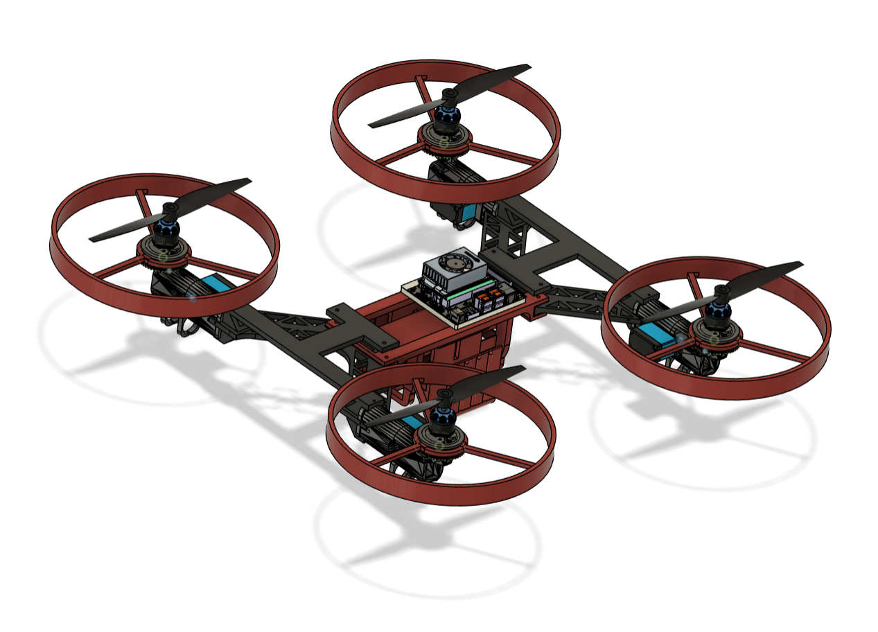
The robot frame and transition mechanisms were 3D printed with PLA. Land navigation was powered by 4 DC motors, mounted on the underside of the robot's arms. The robot's autonomy was powered by a Unitree 4D Lidar L2 and an NVIDIA Jetson Nano using ROS2 and interfacing with a Pixhawk 6C for flight and a Teensy 4.0 microcontroller for land drive.
Mechanical Design
Frame Requirements
- Robot weight is less than or equal to 5 kg (11 lb.) (driven by propulsion lead's max prop thrust of 10 kg)
- Frame must support flight hardware (driven by electrical subteam hardware selection)
- Frame must be able to allow arms to be installed and replaced easily (driven by arm design)
The frame was developed using Fusion360, with its FEA performed on it to test response to propeller thrust of 2.5 kg (5.5 lb.) on each arm. The total thrust of the drone's props was 10 kg, from which we derived our max weight requirement. The factor of safety of 2 is admittedly arbitrary - ChatGPT recommended it. Topology optimization was performed to optimize for mass below this weight. Fasteners are used to connect the arms to the frame, allowing for easy install. Removable arms were chosen given the frequency of arm design updates, the size of prints being too large to fit continuous pieces, and easy replacement of broken members during testing.
The frame conformed to all requirements. It weighed 4 kg (8.8 lb.) including all other hardware, allowed mounting of avionics and BMS, and permitted easy installation and replacement of arms.
Arm Requirements
- Motors must be able to drive wheels about arm longitudinal axis in drive mode
- Wheel/propeller ends must be able to rotate 90 degrees from perpendicular to ground to parallel
- Wheel outer diameter must be greater than props', such that they do not hit the ground
- Arms must be able to withstand 2.5 kg (5.5 lb) of thrust at ends (driven by propulsion lead's max prop thrust of 10 kg)
- Arms must be able to support the robot when driving
The arm design was the core of the project. The difficulty was providing the motions necessary without impairing wiring.
To actuate the 90 degree rotation of the ends, I selected a rack and pinion system. This was chosen due to the high torque density of gear systems, reliability and compatibility with hardware we already had (25kg servos). We tested and ruled out bevel gear systems due to their complexity and redundancy - we would need twice as many actuators for its desgin. An ABENICS (Active Ball Joint Mechanism With Three DoF) setup was tested, but it was overruled due to its complexity and poor power transmission. The rack and pinion system functioned by having a servo drive the pinion gear, and the rack was linked with the connector. Below, the black cross-sections show where the rack and pinion are. The rack was connected to the piece supporting the wheel and motor, and its motion powered the end rotation.
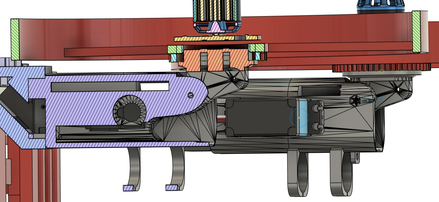
The ends of the arms were designed to allow wheel rotation and well as be driven by small motors, while also mounting the drone motors with rotors spinning coxially with the wheels. The wheels had teeth on their underside, which would mesh with gears on their respective motors when in drive mode.
The wheels successfully meshed with the drive gears in drive mode, and could be driven. The ends successfully rotated 90 degrees when the robot was suspended. Further testing was unable to be completed, as explained in outcomes.
Avionics Hardware Selection
Requirements
- Compatible with ROS2 (driven by software team selecting this software for autonomy)
- Robot records location (software team requirement)
- Robot has wireless two-way communication with control node (electrical team requirement)
The driving reasons for the selection of this hardware were function, resource, and availabilty. The Pixhawk 6C is fully compatible with PX4 Autopilot and can be integrated with ROS2 using the official PX4 ROS2 architecture. In addition to its compatibility, Pixhawks have more documentation online than alternatives and is one of the most mainstream drone flight controllers. I had a connection in the Virginia Tech Unmanned Systems Laboratory, and was able to choose and borrow hardware. I took out a kit including the Pixhawk 6C, a GPS module, and transceivers, though the electrical team selected the ESCs and motors. This allowed the electrical subteam to start designing the BMS, and the software team to start developing simulation.
The ideal functioning robot: the Pixhawk 6C flight controller interfaced with an NVidia Jetson Orin Nano, as well as a GPS sensor and applicable radios for telemetry, ground controller communication, and teleop. To transition between modes, the rotors would rotate as necessary and the appropriate control system will take over (e.g. Jetson will use either Pixhawk or Teensy.) Outcome explains why there will be no video showing this
Outcome
A battery explosion in the lab destroyed this robot. An adjacent team's battery was next to our workstation, and destroyed our hardware. As such, we did not get to complete this project.
This project faced many difficulties. For the first half of the school year, the robot was being designed to include a third aquatic mode. I had worked on this once I was on the team. I devised an experiment to test the validity of a ballast system (simplely designed, using a 500 mL syringe, 45kg servo, a rack and pinion system, and an ESP32 for control and DAQ), but this was ultimately not needed. Our chief engineer left the project around the halfway point, and we had to pivot sharply. Our new lead changed the project to bimodal, and we restarted work. I moved to working on mechanical design. The electrical team hardware selections (e.g., motors, battery) drove mechanical design, and we had to work fast to provide the software team with a URDF file they could use in simulation. In this speed, the work was not refined.
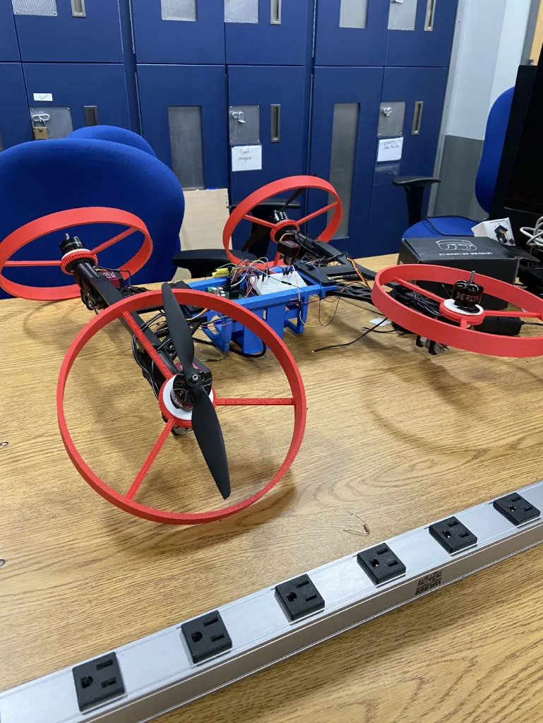
When the battery destroyed our work, the project was crippled. The above picture shows the final state of the robot, which was used for a demo of arm functionality. With our flight hardware destroyed, the robot never flew.
I was unsatisfied with the conclusion of the project, and I want to make changes. I was promoted to the CROLabs mechanical lead role, and I want our work this year to eclipse that of last year (see project HIVE). We recently finished recruitment. Between individual headhunting and outreach events, we received 192 applications to our team, more than double the amount of the previous year. I look forward to us all revamping CROLabs before my graduation this spring.